Tutorial: How 3-way and 4-way switch circuits work
Controlling a light with two or more switches
This page describes how to use 3-way and 4-way switches to control lights from two or more locations. This is the first of several related pages explaining how to control lights with multiple switches. Click here for an overview of all these pages.
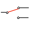
A light or lights can be controlled by more than one switch. The usual practice in home construction is to use 3-way switches. "3-way" is the electrician's designation for a single pole double throw (SPDT) switch.
A 3-way switch is shown below. Slide your mouse over it to see it change state (requires Javascript enabled):
Here is a typical circuit in its four possible states.:
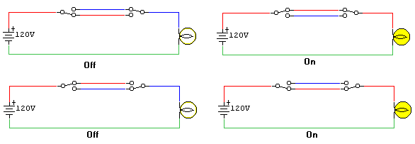
The switches must create a complete circuit for current to flow and the bulb to light. When both switches are up, the circuit is complete (top right). When both switches are down, the circuit is complete (bottom right). If one switch is up and one is down, the current reaches a dead end, no current flows and the bulb is off (top left and bottom left).
Note that the above color scheme does NOT reflect wire color. It is functional coloring intended to illustrate the voltage state of each wire segment.
- Red indicates a hot wire (120 volts ac).
- Green indicates a neutral wire at ground potential.
- Blue indicates a wire that is floating. "Floating" here means isolated from hot and neutral by switches and/or light bulbs.
For choosing wire color for your circuit, see later in this page..
Controlling a light with three or more switches
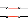 For
more than two switches, one or more 4-way switches are added between the 3-way
switches. A 4-way switch has two positions. In the first position, the contacts
are connected straight through, so that the switch has no effect. In position
two, the switch cross connects the contacts on the left with the contacts on
the right, in an "X" connection. Slide your mouse over the image to
see the switch change state (if you have Javascript enabled in your browser).
To view an animation showing how this works in a complete circuit, see How 4-way switches work -- an animation. This one-minute animation is the clearest illustration of the function of three- and four-way switch function. (Don't worry about file size -- it should download in seconds even via a modem.)
Below is one example of a four-switch light circuit. This circuit also shows rough-in boxes, wire nuts, and proper color code.
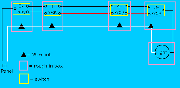
Note that the light can be placed anywhere in the return wire, shown above as white. It may be as shown at the end of the run, but it may be between any pair of switch boxes (as shown in a later figure), or even between the panel and the first switch box. You can use as many 4-way switches as you like.
Color coding
For the official word, consult the National Electric code. Here I will try to describe a bit of what the color coding is about, and how wires should be colored in lighting circuits (and why).
Common practice in wiring a multiswitch circuit is to use two-conductor (black and white) cable from panel to the first switch, and then three-conductor (black, red, white) cable between pairs of switches. White denotes neutral, a current carrying wire that is bonded to ground in the circuit breaker panel. Black and red are used for "hot" conductors 120 volts with respect to ground. The previous figure shows a circuit that follows this convention.
The NEC allows certain exceptions to this in lighting circuits, so that standard two-conductor (black and white) and three-conductor (black, red, and white) can be used, and used efficiently. In particular, it is often convenient and efficient to place a light between two switches or between the panel and the first switch. In such cases, it is convenient and permissable to bring 120 volts to a switch via a white wire.
If you place a light in such a location, please be aware of the confusion that can occur from this wire color. In the above picture, white is always neutral, while black or red may be hot. If the light is located between the middle two switches, then the white wire leading from the light to a switch is, in fact, sometimes hot. To avoid confusion and to conform to code, use a black marker to mark any "hot" white wire feeding a switch. Such color coding is shown in the following example:
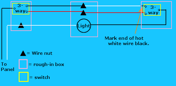
Other variations
Here are another couple of variations of 3- and 4-way switch circuits. All the 4-way switches are optional. If you only need two switches, leave out both the 4-way switches. You can also add as many 4-way switches as you like in place of any one shown in the circuits that follow.
Here is an example of a light in the middle of the run. Notice the pattern is very similar, but the color code is a little trickier. Two of the white wires must be remarked black where the feed the switches.
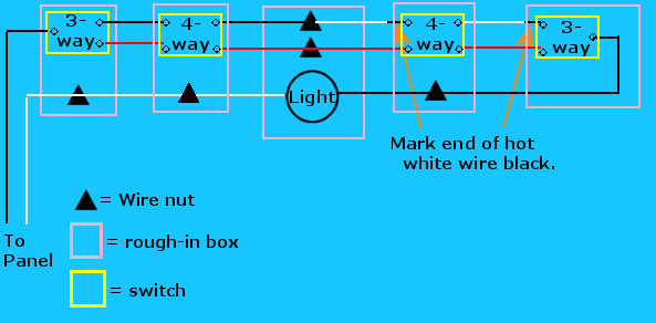
By marking the wire as above, you are informing anyone working in the box later that this is the wire that will deliver (occasionally) 120 volts to the switch. This will enable the worker to properly wire replacement switches. (For circuits with only two switches, just ignore the 4-way switches in the above figure.)
Here is one more variation, with the cable from the panel going directly to the light box, which is in turn between some of the switches..
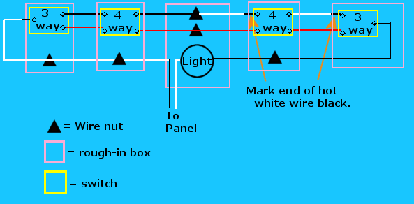
- More variations of 3-way (two switch) circuits.
- More variations of 4-way (three or more switch) circuits.
<Main switches page | <Next lesson : 4-way switches -- an animation>
Related pages:
- 3-way switches and 4-way switches. This is the main page of this collection.
- 4-way switches -- an animation. My clearest description of how three and four-way circuits work
- 3-way switch variations. A collection of several different arrangements of lights and two switches.
- What if you want to control more than one light? See Multiple lights with multiple switches.
- Disconnected your switches and cannot figure out how to put them back? See My 4-way switches don't work or My 3-way switches don't work.
- For other electrical wiring questions, visit the excellent Electrical Wiring FAQ.
- Physics 230
- Miscellaneous tips and info
- Rick Matthews
