Due
Email me emergency contact information for use in case of pandemic.
From your first year physics text, review:
- Resistance.
- Power.
- Resistors in series and parallel.
- Kirchoff's Laws.
- Capacitors and capacitive impedance.
- Inductors and inductive impedance.
Problems:
Find Vout as a function of Vin and the resistor values for the following circuit:
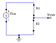
Check your answer in for selected cases in CircuitMaker.
Now find Vout as a function of Vin, R1, and R2 for the following circuit:
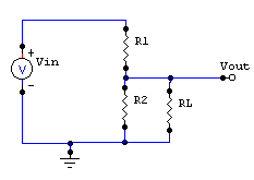
What value of RL in the above circuit causes the Vout to be half the value of Vout for the no-load condition?
Note that in every case, Vout is equal to the voltage across R2.
What value of RLdraws the most power from the circuit? (Hint: P = VI. Express P as a function of RL, and treat this as a minimization problem.)
Be prepared to discuss.
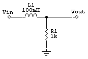
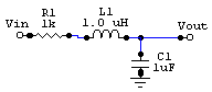
Derive Vout for each of the following circuits. For Vin = 1 volt peak and a frequency of 1 kHz, confirm your calculation using Circuit Maker.
From the end of chapter 1 of the text, problems 3, 4, 5, 6. Scratch and rumble filters are used in conjunction with turntables, which play the "records" that your great-grandparents listened to instead of MP3s. A scratch filter is a low pass filter that removes the high frequency clicks of record scratches. A rumble filter is a high pass filter that removes the very low frequency rumbles from the motor and belts of the turntable.
The load impedance of problems 3 and 4 will be a resistance attached to the output of your filter. The circuit behavior should not be much affected by whether the load is connected or not.
In problem 5, you should think about the shortcut ways of viewing capacitors and/or inductors that we discussed at the end of the last class. This takes a little creativity. Have fun.
For problem 6, realize that you can build a bandpass filter by cascading a low pass and a high pass.
Turn in all answers in as CircuitMaker circuits by e-mail. Name the file with your last name and the set number, i.e., matthews-hw4p3.ckt for set 4, problem 3.
1. Text, Ch.1, problem 7.
2. Design a zener regulator circuit to provide 5V dc to a load that varies between 2 ohms and 10 K. Assume that the input to the regulator is 8V.
- What is the power dissipation in the zener at each of the extremes of load resistance?
- Do you anticipate any problems in using zener regulator for such applications?
- Now design your circuit for a load resistance that varies between 10K and 500K.
- What is maximum power dissipation in the zener for this case?
- Confirm the operation of your last circuit in CircuitMaker.
This last exercise should show you why zener regulators are great for providing a constant voltage to a light (high-resistance) load, but not very practical for providing a constant voltage to a heavy load.
Also, read Chapter 2 of the text through section 2.08.
Using the basic approach from class, design transistor amplifiers with gains of 7,15, and 50. The emitter resistor should stay at 1K, but vary the collector resistor to achieve the intended gain. Use a 2N3904 transistor.
The gain of 15 should work when you test it in CM. Do not be disturbed if the gain of 50 does not work. Can you see why our approach from class becomes unreliable at high gains?
Do NOT submit this assignment. We will build on this for Wednesday's assignment. But be sure you do it, so that you will be able to fully participate in Monday's class. Be prepared to discuss what you learn.
Using the techniques we discussed in class and using a 2N3904 transistor, design a complete, working amplifier for the audio frequency range for each of the following gains:
- 7
- 15
These should work. (Reminder: we are in binary grading mode.)
Using the techniques we developed in class and a 2N3904 transistor, design a complete amplifier for a gain of 50. Does it work? If so, you are a little lucky. Be sure you understand why our current design method is unreliable at high gains. (There is no penalty for this circuit not working.)
Submit each of these circuits in Circuitmaker. As in most assignments henceforth, the first two circuits must work as intended. That is, they should show the intended gain without distortion over the designated frequency range.
- Design a gain of 100 using conservative design techniques discussed in class.
- Now add a load resistor. (You will need a coupling capacitor, of course.) Vary the load resistor to find what value cuts the output voltage in half.
- Do NOT turn in, but be sure you have done this by Monday.